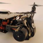

They should be forward on top and backward on the bottom for a push/pull configuration. While the GoPro cage is upright, the dampers are upside down. The roll axis on my build is 180 degrees wrong and should be flipped around. All orange seems to be a good option too. There are reports of vibrations with the standard setup. However, this might change as the dampers need to be fine tuned. For the time being I chose the standard red and orange damper configuration. Otherwise the ends of the zip-ties collided with other parts, preventing the gimbal from turning freely.
#Discovery pro gimbal calibration zip#
The cables are attached with zip ties, which have to be attached exactly how the video shows. Two tiny little grub screws are used to hold the tilt motor. The small electronic board was a little bit too big, but after grinding the board on two ends by fractions of a millimeter it fit snugly into the holder. The small screws are for the metal parts and some of the short bigger ones (from a separate bag) are for the gimbal motors. I’ve started with the gimbal assembly, a big puzzle with motors, screws and aluminum parts.

During the build I got to appreciate zip-ties for fixing all sorts of things, such as the electronic speed controllers (ESCs) onto the arms and the flight camera to the frame. All the electronics and wiring is integrated into the frame and aside from the gimbal and controller, there are only a few cables connecting to individual parts. It’s relatively straight forward to mount the four arms and red spacers to the bottom plate and then close up the sandwich with the top pcb plate.

But now, back to the Discovery Pro.Īfter assembling the gimbal and motors and soldering the bottom plate in the TBS Discovery Pro build part 1, I put all the pieces together. It got a bit delayed because I really wanted to show you the Leistkamm Video before finishing my second quadcopter. This is part 2 of the epic TBS Discovery Pro build.


 0 kommentar(er)
